We at, Prolific Engineers, are
manufacturers, exporters and suppliers of ball resilience tester, resilience tester, flammability testers, fatigue testers, indentation hardness tester, rebound resilience elasticity tester, resilience tester, flammability testing machine, fatigue testing machine, cables & conduits testing equipment in India.
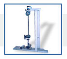
Ball Resiliece Tester
Resilience of polyurethane foam is
determined by dropping a metallic sphere on a slab of foam kept on a
horizontal surface from a height of 500 mm and finding the height to which
it rebounds after striking the surface of foam.
The PROLIFIC Rebound Resilience Tester for polyurethane foam consists of a
flat horizontal platform, a vertical acrylic tube in which the sphere is
dropped, and a hand operated arrangement to release the sphere from a
pre-determined height.
The platform on which the test specimen is kept also forms the base of the
equipment. It has four leveling screws to make it horizontal.
The acrylic tube is held over the base with the help of a holding block,
which can be moved vertically to adjust the height of the tube to enable
test specimens of different thicknesses to be tested. This adjustment is
carried out with the help of a screw so that the height of the tube can be
precisely set. The tube is held firmly after adjustment so that it does not
rock during the test.
The scale used for measurement of the height of rebound is marked on the
outer surface of the acrylic tube. It ranges from 10% to 90% of the dropping
height.
The metallic sphere is kept in a circular opening in the metallic cover of
the acrylic tube. It can be release by pressing a spring-loaded support,
which is so designed as to release the sphere without imparting any initial
linear or rotary movement to it.
The equipment is finished in grey hammertone stoving painting and bright
chrome plating to give it a corrosion resistant finish.
|
TECHNICAL DATA |
|
Diameter of steel sphere |
16 mm |
|
Weight of steel sphere |
16.3 g |
|
Dropping height |
500 mm |
|
Height of test specimen |
50 to 150 mm |
|
Inner diameter of acrylic tube |
40 mm |
|
RELATED STANDARDS |
|
ASTM D 3574 - 1986 |
Standard Methods of Testing Flexible Cellular
Materials - Slabs, Bonded, and Moulded Urethane Foam |
|
ISO 8307 - 1990 |
Flexible Cellular Polymeric Materials -
Determination of Resilience |
|
JIS K 6400 - 1997 |
Test Methods for Flexible Polyurethane Foam |
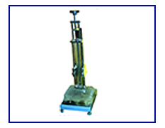
Indentation Hardness Tester
The feel of softness of any flexible
foam is quantitatively defined by its indentation hardness. Indentation
hardness of foam is determined by pressing a circular indentor at a
specified speed against a block of foam and finding the force needed to
compress it to a specified percentage of its initial thickness.
The PROLIFIC Indentation Hardness Tester for polyurethane foam consists of
a circular indentor which can be pressed against the foam block under test,
a motorized arrangement to move the indentor, and a load indicating
arrangement to indicate the load being exerted by the indentor on the foam
block at any instant.
The indentor is in shape of a circular disc and is mounted on a
self-aligning ball bearing to ensure that it sits parallel to the surface of
the test specimen. It is mounted at the lower end of a screw, which can be
raised or lowered at a specified speed with the help of a motor and worm
reduction gearbox. An arrangement to stop the motor at extreme ends of
travel of the indentor is provided.
The downwards movement of the indentor is measured with the help of a
pre-set type digital displacement meter, which can be set at any desired
value to stop the motor automatically at a desired displacement. A linear
scale is provided to indicate the gap between the bottom face of the
indentor and the loading platform. The indentor can also be moved by hand to
apply the initial load.
The load platform is made of cast aluminium and has a large number of holes
arranged in a grid for rapid escape of air during compression. It is mounted
on shear beam type load cell. A digital load indicator is provided to
indicate the load acting on the test specimen.
The equipment is finished in grey hammertone stoving painting and bright
chrome / zinc plating to give it a corrosion resistant finish.
|
TECHNICAL DATA |
|
Area of Indentor |
323 cm² |
|
Diameter of indentor |
202.8 mm |
|
Maximum thickness of test specimen that can be
tested |
150 mm |
|
Measurement of load |
0 - 100 kg x 0.1 kg |
|
Measurement of travel |
0 - 150 mm x 1mm |
|
Speed of movement of indentor |
150 mm/minute * |
|
Motor |
¼ HP single-phase 230 volts AC |
|
RELATED STANDARD |
|
IS 7888 - 1976 |
Methods of Test for Flexible Polyurethane Foam |
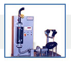
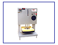
The effect of repeated application of
pressure on the surface of a slab of polyurethane foam experienced in its
normal life is evaluated by simulating these conditions in laboratory by
applying and releasing a specified force for a specified number of times,
after which the effect of such pounding on the physical characteristics such
as hardness index, thickness, and cell structure are observed to evaluate
the quality of foam slab.
The PROLIFIC Pounding Tester for polyurethane foam consists of a flat
metallic platform for keeping the test specimen on, a circular indentor of
specified shape and size which can be repeatedly lifted off and pressed
against the foam slab, a motor operated arrangement to give movement to the
indentor, and a counter to count the total number of poundings given to the
test specimen.
The full force is applied to the specimen by the dead weight of the
indentor. Suitable means have been provided to control the time for which
the full force is applied. The time for load application shall not be more
than 25% of the total duration of each cycle.
The horizontal platform is made from aluminium casting and has a number of
holes drilled in it for the air to escape through.
The indentor is circular in shape and has a rounded edge to prevent damage
to the test specimen during the test. It is moved along a vertical axis with
the help of an eccentric and link arrangement. Movement to the indentor is
given through two sets of V-belts and pulleys.
The height of the indentor can be adjusted to ensure that it is just lifted
off the top of the test specimen at its highest point. Its movement can be
adjusted between 20 and 50 mm. The movement is so adjusted that the indentor
rests freely on the test specimen at the lower limit of its travel, thus
exerting only the force due to its mass. Provision of over-travel of the rod
on which that indentor it mounted ensures that the load does not exceed the
specified value during the test.
A five digit pre-set type electronic counter with memory back-up is
provided to count the number of poundings given to the test specimen and
also to stop the motor after the desired number of poundings.
The equipment is fabricated over a rigid metallic frame and is finished in
grey hammertone painting and bright chrome / zinc plating to give it a
corrosion resistant finish.
|
TECHNICAL DATA |
|
Dimensions of test specimen |
380 x 380 x 50 mm |
|
Diameter of indentor |
250 ± 1 mm |
|
Number of specimens |
One |
|
Radius at edge of indentor |
25 ± 1 mm |
|
Movement of indentor |
Adjustable between 20 and 50 mm |
|
Mass of indentor assembly |
76.45 ± 2 kg (force applied - 750 ± 20
N) |
|
Pounding frequency |
70 ± 2 cpm |
|
Motor |
½ HP single-phase 230 volts AC |
|
RELATED STANDARDS |
|
ASTM D 3574 - 1986 |
Standard Methods for Testing Flexible Cellular
Materials - Slabs, Bonded, and Moulded Urethane Foams |
|
ISO 3385 - 1989 |
Flexible Cellular Polymeric Materials -
Determination of Fatigue by Constant-Load Pounding |
|
JIS K 6400 - 1997 |
Test Methods for Flexible Polyurethane Foam |
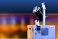
Shear Fatigue Tester
The ability of polyurethane foam slabs
to withstand the effect of repeated compressions is determined with the help
of a shear fatigue test. In this test, test specimen in shape of a square
block is held over a flat reciprocating platform and is pressed down from
the top by a horizontal cylindrical roller inclined at an angle of 15° to the direction of motion of the platform. The platform is moved for a
specified number of cycles and the effect of repeated compressions produced
on the test specimen is evaluated by finding the change in its thickness and
indentation hardness index.
The PROLIFIC Shear Fatigue Tester for polyurethane foam consists of a
reciprocating platform on which the test specimen can be held, a cylindrical
roller to compress the test specimen, and an arrangement to either produce a
constant deflection of the test specimen or to apply a constant load on it.
The reciprocating platform is made of cast aluminium and is moved in a
horizontal plane with the help of a motor, worm reduction gearbox, and a
link. It moves on four wheels having ball bearings. The wheels run on two
metallic rails. The platform has a large number of holes on its upper
surface for rapid escape of air during compression. The test specimen is
held on the platform with the help of either a double-sided adhesive tape or
by holding fabric strips pasted on its ends under two bar shaped grips.
The cylindrical roller is made of stainless steel and rests on the surface
of the test specimen. Its axis is inclined at 15° to the direction of
motion of the platform. The roller is mounted on two ball bearings and is
held on the ends of two levers to permit a hinged vertical movement.
The desired deflection is given by placing dead weights above the
cylindrical roller. Test under constant deflection are conducted by
restricting the vertical movement of the roller with the help of two
adjustable knurled bolts. Tests under constant load are conducted by placing
desired dead weights above the roller.
A five digit pre-set type electronic counter with non-volatile memory is
provided to record the number of compression of the test specimen and to
automatically stop the motor after the desired number of compressions.
The apparatus is finished in grey hammertone stoving painting and bright
chrome / zinc plating to give it a corrosion resistant finish.
|
TECHNICAL DATA |
|
Flexing frequency |
28 cpm |
|
Movement of platform |
330 mm |
|
Dimensions of the roller |
75 mm diameter, 460 mm length |
|
Dimensions of test specimen |
380 x 380 mm |
|
RELATED SPECIFICATIONS |
|
IS 7888 - 1976 |
Methods of Test for Flexible Polyurethane Foam |
|
ASTM D 3574 - 1986 |
Standard Methods of Testing Flexible Cellular
Materials - Slab, Bonded, and Moulded Urethane Foams |
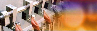
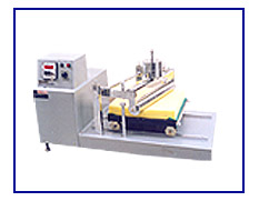
Out-soles of footwear or other flexing
components may suffer cracking due to flexing in use. Cracks usually develop
at points of high surface strain resulting from the design of the sole
pattern, without there are being any cuts due to grit etc. to initiate them.
The belt flex tester is designed to flex complete soles with their patterns
intact in a way similar to flexing in actual use. Tests carried out using it
provide a guide to the risk of such cracks developing during use.
In this test, test specimens are attached to the outside of a continuous
belt, which is driven round two rollers. The larger roller drives the belt,
while movement of the belt round the smaller roller provides the main
flexing action. The radius of the smaller roller is chosen to make the
flexing either more severe or less severe than in actual use.
This form of flexing also copies the wear conditions at each step as it
produces a short period of rapid flexing followed by a longer period when
the specimen is not being flexed. A normal test consists of a number of
flexing runs up to a total of 50,000 flexes, with an examination for
cracking at the end of each run.
The PROLIFIC Belt Flex Tester consists of two rollers on which a flat belt
moves. The larger roller, which is the driving roller, rotates at a desired
speed with the help of an electric motor and V-belt arrangement to give the
specified frequency of flexing. The second roller, which is the flexing
roller, rotates with the movement of the belt.
The flexing rollers are slightly barreled shaped so as to minimize sideways
movement of the belt. A hand wheel is attached to the front end of these
rollers to enable the belt to be moved by hand. The equipment is supplied
with three flexing rollers, one for normal soles, the second for very
flexible soles, and the third for very hard soles.
The distance between the two rollers can be adjusted with the help of a
screw arrangement to enable the belt to be mounted over different flexing
rollers and to allow for small differences in belt length. This is done by
turning a hand wheel on the side of the tester.
The tester is provided with an acrylic front cover and a sheet metal safety
guard, which allows adequate circulation of cooling air round the test
specimens during the test. The motor can be started only when the acrylic
cover is closed.
A six digit pre-set type electronic counter with memory backup and an
inductive sensor are provided to record the total numbers of cycles
completed by the belt and thus the number of flexes undergone by the test
specimens mounted on it. The motor stops automatically on completion of the
set number of flexes.
The apparatus is finished in grey hammertone stoving painting and bright
chrome / zinc plating to give it a corrosion resistant finish.
|
TECHNICAL DATA |
|
Dimensions of driving roller |
220 ± 10 mm diameter, 170 ± 20 mm length |
|
Dimensions of flexing roller for normal soles
|
90.0 ± 0.5 mm diameter at centre / 87 ±
1.0 mm diameter at ends, 170 ± 20 mm length |
|
for very flexible soles |
60.0 ± 0.5 mm diameter at centre / 57 ±
1.0 mm diameter at ends, 170 ± 20 mm length |
|
for very hard soles |
120.0 ± 0.5 mm diameter at centre / 117 ±
1.0 mm diameter at ends, 170 ± 20 mm length |
|
Number of flex per minute |
90 ± 8 flexes/minute |
|
Motor |
¼ HP single-phase 230 volts AC |
|
Counter |
Six digit electronic counter with memory back up,
inductive sensor, and key reset. |
|
RELATED STANDARD |
|
SATRA PM 133 - 1993 |
Resistance to Crack Initiation and Growth - Belt
Flex Method |
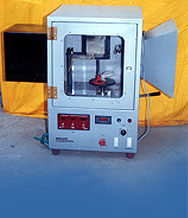
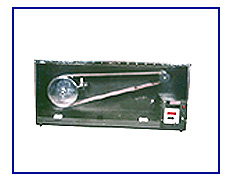
Bennewart flex testing is intended to
determine the resistance of a component of material to cut growth during
repeated flexing. It can also be used to assess the effect of surface
patterns on crack initiation and growth. This test is especially applicable
to the outsoles of footwear, but may also be used with certain other
flexible components.
The PROLIFIC Bennewart Flex Tester consists of a drive unit comprising of
an electric motor with pulleys and belts system to give the desired speed to
an eccentric and link mechanism to give an oscillating movement to one of
the two grips holding the two ends of test specimens, the other grip being
fixed.
The oscillating grip has gun metal bushes, which slides on two hardened and
ground bearing steel rods to give it a long working life. Each grip consists
of swivable bases pivoted on ball bearings so that the two ends of the test
specimens are free to align themselves with the natural contour of the
specimen during flexing.
The axis about which the grip bases oscillate lies in the plane of their
specimen holding face. A six digit pre-set electronic digital counter counts
the numbers of test cycles and also stops the motor after pre-set numbers of
test cycles.
The apparatus is finished in grey hammertone stoving painting and bright
chrome / zinc plating to give it a corrosion resistant finish.
A cutting die for preparation of test specimen from sheet and slitting
punch with jig for making initial crack are available as optional
accessories.
|
TECHNICAL DATA |
|
Number of test specimens tested |
2 for full sole, 6 for cut test specimens |
|
Angle of flexing |
90° |
|
Diameter of bending mandrel |
30 mm |
|
Frequency of operation |
125 to 150 cycles/minute |
|
Motor |
½ HP single-phase 230 volts AC |
|
Counter |
Six digit pre-set type digital type with memory
backup |
|
RELATED SPECIFICATIONS |
|
DIN 53543 1979 |
Testing of Semi Rigid Polyurethane (PUR) Integral
Cellular Materials Materials for Soles and Parts of Shoes |
|
SATRA PM 161 |
Bennewart Flex Test Resistance to Cut Growth on
Flexing |
|
IS 15298 (Part 1) -2002 |
Safety, Protective and Occupational Footwear for
|
|
ISO 8782 (Part 1) - 1998) |
Professional Use Part 1 : Requirement and Test
Method |
|
BS EN 344 - 1993 |
Requirement and Test Methods for Safety,
Protective, and Occupational Footwear for Professional Use |
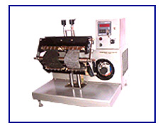
The shoe flex tester is used for
determination of the ability of the full shoe to withstand the effect of
flexing stresses produced on the different parts of the shoe. Although the
various parts like uppers and soles of a shoe are tested separately for
flexing endurance with the help of flexometer and Ross flex tester, the shoe
flex tester gives results, which are more related to the actual performance
of the shoe as a whole.
The PROLIFIC Shoe Flex Tester simulates the effect of actual walking action
on the shoe. The test specimen is held rigidly at the toe portion using a
suitable toe last and clamp, while the heel portion has a separate last on
which the shoe is firmly tied as in actual use.
The upper end of the sslast has an arrangement to connect a suitable link
mechanism. The link mechanism is connected to an eccentric pin on a rotating
block to give the link a to-and-fro movement. Both the eccentricity of the
pin in the block and the length of the link are adjustable to give various
angles of deflection of the shoe with respect to the flat portion of the
toe, which is rigidly held by the clamp.
Movement to the rotating block is given by means of a motor and two-stage V
belt and pulley arrangement. A pre-set type digital counter with key reset
and memory backup is provided to record the total number of test cycles and
to stop the motor automatically after pre-set number of test cycles.
The apparatus is finished in grey hammertone stoving painting and bright
chrome plating to give it a corrosion resistant finish.
|
TECHNICAL DATA |
|
Flexing frequency |
140 ± 10 cycles/minute |
|
Maximum angle of flexing of shoe |
45° |
|
Number of shoes tested at a time |
Two |
|
Motor |
¼ HP single-phase 230 volts AC |
|
Timer |
Digital timer of range 99.9 s having a resolution
of 0.1 s, with three displays and push button controls to indicate
various times |
|
Counter |
Six digit pre-set type electronic counter |
|
RELATED STANDARDS |
|
SATRA PM92 |
Resistance of Footwear to Flexing |
|
IS 8085 (Part 2):1999 |
Method of Test for Footwear (Part 2) Footwear
Performance Test, Stiffness Test for Shanks; Lastometer Test for
Cracking of Uppers; and Performance Test for Upper Fabrics, Coated
Fabrics, Sock Lining and other Lining Materials |
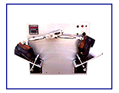
The ability of light leathers and
leather-cloth used in manufacture of shoe uppers, gloves, and garments to
withstand repeated flexing without cracking is determined with the help of a
flexing endurance test.
In this test, test specimens in shape of rectangular pieces are folded and
clamped at each end to maintain them in a folded position in a set of grips,
one of which is fixed while the other is able to oscillate. The movement of
the oscillating grip causes the fold in the test specimen to run along its
centre. This operation is carried out repeatedly and the test specimens
inspected periodically to assess the damage produced. The equipment used for
this test is called as Flexometer.
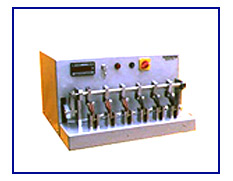
The PROLIFIC Flexometer is built on a rigid metallic base plate. Test
specimens are held between a pair of stationary and oscillating grips. The
grips are specially designed to enable quick fixing and removal of test
specimens and are shaped to meet the specification of the test.
Motion to the oscillating grips is given through a link mechanism, which
oscillates the shaft on which the grips are mounted. All the pivot points of
the mechanism have ball bearings to ensure smooth operation and a long
working life.
The link mechanism is give motion from an electric motor and two sets of
V-pulleys. A six-digit electronic counter with key-reset and backup memory
is provided to record the total number of flexing cycles undergone by the
test specimens.
The apparatus is finished in bright chrome / zinc plating and grey
hammertone stoving painting to give it a corrosion resistant finish.
The standard model of flexometer can test upto six specimens at one time.
Special models capable of testing either twelve or twenty-four test
specimens at one time can also be offered against specific requirements.
Specimen cutting die and cutting press are also available as optional
accessories.
|
TECHNICAL DATA |
|
Angle of oscillation of grips |
22.5° ± 0.5° |
|
Flexing frequency |
100 ± 5 cycles/minute |
|
Dimensions of test specimens |
70 x 45 mm |
|
Maximum number of test specimen that can be tested
at one time |
Six, twelve, or twenty-four |
|
Motor |
¼ HP single-phase 230 volts AC |
|
RELEVANT SPECIFICATIONS |
|
IS 5914 - 1970 |
Methods of Physical Testing of Leather
LP 19 : Flexing Endurance |
|
BS 3144 - 1968 |
Methods of Sampling and Physical Testing of
Leather
Clause 13 : Measurement of the Flexing Endurance of Light Leather and
their Surface Finishes |
|
IUP / 20 - 1963 |
Official Methods of International Union of Leather
Chemists' Societies |
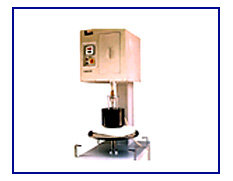
Martindale Abrasion Tester
Determination of resistance of any
fabric to abrasion is usually carried out by abrading the fabric under
specified conditions against a standard abradant. Although plane abrasion of
fabric surface does not cover all aspects of strains that are important in
determining service life, there are occasions when such a test gives useful
information.
One of the standard equipment used for this determination is the Martindale
Abrasion Tester. This apparatus gives a controlled amount of abrasion
between fabric surfaces at comparatively low pressures in continuously
changing direction. Circular specimens of fabric are abraded under known
pressures under a motion which is the resultant of two simple harmonic
motions at right angle to each other. The resistance to abrasion is
estimated by visual appearance or by finding the loss in mass of the
specimens.
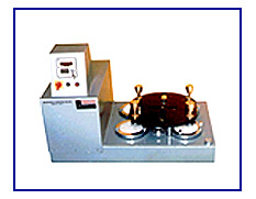
The PROLIFIC Martindale Abrasion Tester consists of a plate which is give a
motion combining two harmonic motions at right angle through three rotating
eccentric pegs, four number specimen holders for mounting the fabric under
test on, and four number abradant holders against which the test specimens
are abraded.
The plate is supported on three oil-lubricated felt discs and has three
slots for locating the eccentric pegs in. The pegs are rotated with the help
of an electric motor, worm reduction gearbox, and sprockets and chain
arrangement such that the central peg is rotating at a slower speed than the
two outer pegs, which rotate at the same speed. The movement of the pegs
causes the plate to move in two mutually perpendicular directions in simple
harmonic motions, thus providing the necessary abrading action.
The test specimens are mounted on flat metallic discs and are backed with a
thin layer of polyurethane foam. The shafts of the specimen holders are
guided vertically in bushes on the moving plate. Thus the movement of the
plate causes the specimen holders to move with the plate, abrading it
against the abradant fixed mounted in four holders located below them. The
force on the test specimens can be altered by adding or removing dead
weights from the specimen holders.
A five digit electronic pre-set counter counts the number of rotation of
outer pegs and stops the motor automatically after a pre-set numbers of
rotations. Templates for marking the test specimens and abradant, disc
weights to keep them flat during fixing, and mounting jig for test specimens
are provided as standard accessories.
The various components are mounted on a sturdy fabricated steel base and
are finished in grey hammertone stoving painting and bright chrome or zinc
plating to give them a corrosion resistant finish.
|
TECHNICAL DATA |
|
Maximum number of test specimens that can be
tested at a time |
Four |
|
Speed of outer pegs |
47.5 ± 2 rpm |
|
Ratio of speeds of outer pegs to central peg
|
32 / 30 |
|
Stroke of pegs |
60.5 mm |
|
Working area of specimen holder |
6.45 cm² |
|
Pressure on test specimens |
Pressure on test specimens |
|
RELATED STANDARDS |
|
IS 12673 - 1989 |
Textile Fabrics - Abrasion Resistance - Methods
for Determination |
|
BS Handbook 11 |
Method of Test for Abrasion Resistance of Fabrics |
|
IS: 15298(Part 1)-2002
(ISO 8782-1 - 1998) |
Safety, Protective and Occupational Footwear for
Professional Use
Part 1 : Requirement & Test Method |
|
BS EN 344 - 1993 |
Requirement and Test Methods for Safety,
Protective, and Occupational Footwear for Professional Use |