We at,
Prolific Engineers, are manufacturers, exporters and suppliers of adhesion testers, adhesive testing equipment, automobile accessories testing equipment, building hardware testing equipment, cables & conduits testing equipment in India.
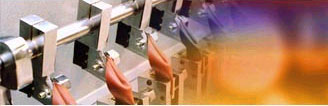
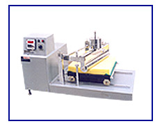
Rotary Drum (DIN) Abrasion Tester
In applications where an elastomer is subjected to frequent rubbing or abrasive actions as part of its use, it is of prime importance to ensure that the formulation used has a fair degree of resistance to abrasion.
One of the methods for determining the abrasion resistance of elastomers is by a Rotating Drum Abrasion Tester. In this test the elastomer under test is abraded against an abrading surface mounted over a rotating drum. The abrading surface has a specified abrading power. The test specimen, which is in form of a button, is held against it under a fixed load. The abrading surface is made to rub against the test specimen by rotating the drum at a fixed speed, the test specimen being meanwhile made to move along the axis of the drum.
The ratio of the volume loss of a standard elastomer to the volume loss of the rubber under test, determined under the same conditions and expressed as a percentage, gives the abrasion resistance index of the rubber under test.
The determination of volume loss by this method is suitable for comparative testing and for checking the uniformity of specified products. However, the results of this test give only limited information on the wearing behaviour of elastomers in practice.
The PROLIFIC Rotating Drum Abrasion Tester is designed to determine abrasion resistance index of natural and synthetic rubbers in accordance with the above principle. It consists of test specimen holder with a cylindrical opening adjustable between 15.5 and 16.3 mm to clamp the test specimen, with an arrangement to adjust the length of test specimen protruding out.
The holder is mounted on a swivable arm pivoted in a bracket, which is moved laterally by a screw mechanism along the length of a rotating drum on which the abrasive cloth is fixed. The test specimen holder also provides an arrangement to protect the abrasive cloth from damage by preventing the lower edge of the test specimen holder to touch the abrasive cloth.
The movement to the screw mechanism and the drum is given by an electric motor coupled to a worm reduction gearbox with V-belt and pulleys to give the specified speed of rotation to the drum and the specified lateral movement to the test specimen holder. The equipment is provided with limit switches, which, in addition to giving over-travel safety to the movement of test specimen holder, also stop the motor automatically after the specified run of the test specimen.
The swivable arm and test specimen holder are so disposed that the test specimen is pressed against the drum under the specified load with its centre axis at an inclination of 3° to the perpendicular in the direction of rotation and placed above the longitudinal axis of drum.
The abrasive cloth is firmly fixed to the drum using a suitable peelable adhesive with the ends of the abrasive cloth butt jointed together. Four abrasive cloths in addition to the one fixed on the cylinder are supplied with the equipment as standard accessory.
Moulding die and rotary type cutting die (hollow drill) for preparing test specimens and extra abrasive cloths are available as optional accessories.
TECHNICAL DATA |
Diameter of test specimen |
16 ± 0.2 mm |
Height of test specimen |
6 to 10 mm |
Diameter of rotating drum |
150 mm |
Length of rotating drum |
470 mm |
Speed of rotation of cylinder |
40 ± 2 RPM |
Lateral movement of test specimen holder |
4.2 mm per revolution of drum |
Load on test specimen |
10 N / 5 N |
Inclination of axis of specimen holder |
3º from vertical |
Total length of abrading run |
40 m (about 84 rotations) |
Abrasive cloth |
450 mm wide x 473 mm long coated With aluminium oxide abrasive grain of 60 grit |
Motor |
¼ HP - 230 volts AC |
RELATED STANDARDS |
IS 3400 (Part 3) 1987 |
Methods of Test for Vulcanised Rubbers
Part 3 : Abrasion Resistance using a Rotating Cylindrical Drum Device |
DIN 53516 |
Testing of Rubber and Elastomers - Determination of Abrasion Resistance |
ISO 4649 1985 |
Rubber Determination of Abrasion Resistance using a Rotating Cylindrical Drum Device |
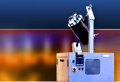
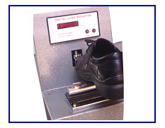
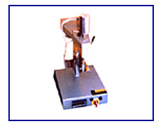
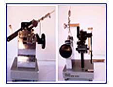
The strength of adhesion of a sole to its upper is determined by measuring the force needed to pull off the sole from the upper. A suitable last is placed inside the shoe, which is then placed on a straight edge acting as a fulcrum for applying load on the joint of the sole and upper. The maximum load the sole can withstand before coming off is determined and reported as the sole adhesion strength. This test can be carried out either at the heel or at the toe of the shoe.
The PROLIFIC Sole Adhesion Tester consists of a cantilever type load cell with a digital readout to measure and indicate the force applied at the junction of the sole or heel and the upper and a set of interchangeable toe pieces having different curvatures.
The load cell measures the force applied on the joint, which is indicated directly in kilograms on a digital readout with a peak force memory to indicate the maximum force applied before the failure of adhesion.
Five toe pieces of different curvatures are provided to enable toes and heels of different shapes and sizes to be tested. The length of arc of each toe piece, however, is the same to ensure that the force is applied only on a fixed length of joint. These are made from carbon steel for giving a long operational life. Any one of the toe pieces can be held in the equipment at one time.
The fulcrum on which the shoe is placed during the test has adjustable height to enable soles of different thickness to be tested. The height of the fulcrum is adjusted with the help of six spacer strips provided with the equipment.
The equipment is finished in grey hammertone stoving painting and bright chrome / zinc plating to give it a corrosion resistant finish.
TECHNICAL DATA |
Force capcity |
0 - 100 kg x 100 g |
Curvatures of toe pieces |
25, 30, 35, 40, and 45 mm |
Length of contact arc |
22 mm |
RELATED SPECIFICATIONS |
IS 8085 (P 1) - 1986 |
Methods of Test - Footwear Part 1 : Dimensions, Fitting, Adhesion Test, Peel Test, Heat Resistance Test, and Ageing Test |
IS 11226 - 1993 |
Leather Safety Footwear having Direct Molded Rubber Sole - Specification |
SATRA AM 4 |
Adhesive Test Method; Test Method for Sole Adhesion Test |
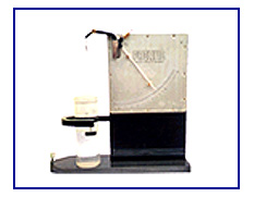
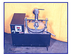
The PROLIFIC Specific Gravity Balance provides a simple and quick mean to read directly the specific gravity of rubber and other elastomers, thus reducing labour and eliminating calculations. The time taken to find out the specific gravity of a sample is only about half a minute.
The balance consists of an anodised scale with specific gravity (SG) printed on it standing vertically on a heavy base plate. A balancing arm is provided at the centre point of the scale. The arm is supported on two jewel bearings to minimise friction.
Two stainless steel pins are suspended from one end of the arm. One of the pins is attached through a short length of yarn and the other through a long length of yarn. The second pin is kept immersed in water inside a tall transparent jar kept on the base.
A pointer is attached at the other end of the balancing arm that indicates the specific gravity of sample under test. A sliding weight is also provided for initial balancing of the samples of different weights. A levelling screw is provided for initial levelling of the base plate.
A sample of any shape can be used for determination of specific gravity. Its weight shall, however, lie between 5 and 15 g. The sample used shall not be soluble in water or be affected by it in any way. If the sample has a cellular structure, the cells shall be of closed type so that the absorption of water is kept at minimum.
Other models of specific gravity balance capable of measuring specific gravity in the range of 0.2 to 2.0, 0.05 to 0.70, and 0.02 to 0.50 are also available. Special models for measurement of specific gravity of liquids and of materials in form of powder or granules are also being manufactured.
CALIBRATION |
From 0.9 to 2.0 |
graduated in divisions of 0.01 |
From 2.0 to 2.5 |
graduated in divisions of 0.02 |
From 2.5 to 3.0 |
graduated in divisions of 0.05 |
The ability of polyurethane foam slabs to withstand the effect of repeated compressions is determined with the help of a shear fatigue test. In this test, test specimen in shape of a square block is held over a flat reciprocating platform and is pressed down from the top by a horizontal cylindrical roller inclined at an angle of 15° to the direction of motion of the platform. The platform is moved for a specified number of cycles and the effect of repeated compressions produced on the test specimen is evaluated by finding the change in its thickness and indentation hardness index.
The PROLIFIC Shear Fatigue Tester for polyurethane foam consists of a reciprocating platform on which the test specimen can be held, a cylindrical roller to compress the test specimen, and an arrangement to either produce a constant deflection of the test specimen or to apply a constant load on it.
The reciprocating platform is made of cast aluminium and is moved in a horizontal plane with the help of a motor, worm reduction gearbox, and a link. It moves on four wheels having ball bearings. The wheels run on two metallic rails. The platform has a large number of holes on its upper surface for rapid escape of air during compression. The test specimen is held on the platform with the help of either a double-sided adhesive tape or by holding fabric strips pasted on its ends under two bar shaped grips.
The cylindrical roller is made of stainless steel and rests on the surface of the test specimen. Its axis is inclined at 15° to the direction of motion of the platform. The roller is mounted on two ball bearings and is held on the ends of two levers to permit a hinged vertical movement.
The desired deflection is given by placing dead weights above the cylindrical roller. Test under constant deflection are conducted by restricting the vertical movement of the roller with the help of two adjustable knurled bolts. Tests under constant load are conducted by placing desired dead weights above the roller.
A five digit pre-set type electronic counter with non-volatile memory is provided to record the number of compression of the test specimen and to automatically stop the motor after the desired number of compressions.
The apparatus is finished in grey hammertone stoving painting and bright chrome / zinc plating to give it a corrosion resistant finish.
TECHNICAL DATA |
Flexing frequency |
28 cpm |
Movement of platform |
330 mm |
Dimensions of the roller |
75 mm diameter, 460 mm length |
Dimensions of test specimen |
380 x 380 mm |
RELATED SPECIFICATIONS |
IS 7888 - 1976 |
Methods of Test for Flexible Polyurethane Foam |
ASTM D 3574 - 1986 |
Standard Methods of Testing Flexible Cellular Materials - Slab, Bonded, and Moulded Urethane Foams |
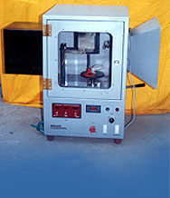
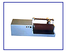
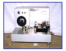
The rub proofness tester is used for determination of fastness of colour of light leathers to wet and dry rubbing and for measuring the transfer of colour to the material with which it is rubbed. The test specimen is rubbed with a rotating circular felt pad pressing against it under a specified force, and the number of revolutions of the pad required to produce certain specified effects is determined.
This equipment can also be used for assessing the degree of damage to a material during mild wet abrasion imitating the scuffing action of a damp hose on footwear insole during wear. A rotating wet circular felt pad, covered with a worsted fabric under a specified contact force rubs against the test specimen. Overall damage to the test specimen is assessed by measuring its mass loss after a specified numbers of rubs.
The PROLIFIC Rub Proofness Tester is constructed on a rigid fabricated frame. Rubbing is carried out by rotating a felt pad against a test specimen placed on an anvil. The felt pad is held in a rotating holder with the help of three sharp needles and can be raised and lowered with the help of a lever to bring it in contact with the test specimen.
Motion to the felt pad is given by an AC synchronous motor and belt-pulley arrangement. The sleeve in which the rod carrying the rotating holder slides is mounted on two ball bearings to give it a long and trouble-free running life. Weights are provided to apply the specified forces on felt pads for both dry and wet rubbing.
The test specimens are normally kept on a flat platform under the rotating felt pad. However, for testing of finished products, provision has been made to replace the flat platform by a small circular anvil that can accommodate various finished products like shoulders of garments and shoes.
A four-digit electronic counter with re-set counts the number of abrading rubs of the felt pad. The counter operates only when the felt pad is lowered on to the test specimen.
The tester is finished in grey hammertone stoving painting and bright chromium or zinc plating to give it a corrosion resistant finish.
TECHNICAL DATA |
Rotating Speed |
150 rpm |
Load on felt pad |
0.73 kg or 2.5 kg |
Motor |
AC synchronous motor - 10 kg.cm |
Counter |
Four digit electronic counter |
RELATED STANDARD |
IS 6191 1971 |
Methods of Micro-Biological Colour Fastness and Microscopical Tests for Leather
LF 9 : Determination of Fastness to Rubbing (Wet and Dry) of Light Leathers |
BS 3662 1962 |
Methods for the Determination of Colorfastness of Leathers |
SLTC SLF/5 |
Determination of Fastness to Rubbing (Wet and Dry) of Light Leathers |
SATRA PM 8 - 1992 |
Colourfastness to Circular Rubbing |
SATRA PM 14 - 1992 |
Resistance to Scuffing by Mild Circular Abrasion |
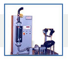
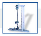
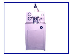
The uppers of shoes get folded over the toe portion every time a step is taken. These repeated folding cause the finished grains to start cracking, resulting in loss of water resistance. To ensure that the leather uppers retain their water resistance for a reasonable period of use, the action of such folding on them is evaluated by subjecting test specimens taken from the leather to a water penetration test using a penetrometer.
In this apparatus the test specimens are held in form of a trough between two cylindrical grips. One of the grips is then repeatedly moved towards and away from the other along their common axis. The test specimens are kept immersed in a water bath up to a part of their periphery. Penetration is detected when an electric conductivity is established between the inside and outside surfaces of the test specimens.
The time needed to cause penetration of water through the test specimens is determined and taken as an index of water resistance of the leather. The test can be further continued to determine the percent gain of weight of the specimen due to water absorption and also to determine the mass of water that is transmitted.
The PROLIFIC Penetrometer for leather for shoe uppers consists of a set of acrylic cylindrical grips, half of which are fixed while the remaining half are movable along their common axis. The movement to the grips is give with the help of a motorized arrangement through a worm reduction gearbox. The travel of moving grip, which is different for different leathers, can be set at any one of the four specified values by changing the cam fitted on the gearbox.
The grips are located inside a rectangular water container. The container can be filled with water upto the desired level after fixing the test specimens. An overflow pipe is provided to keep the level of water at a predetermined height. A draining arrangement is also provided to empty out the container at the end of the test.
Each of the test stations has a provision for setting up an electric contact between spiral brass turnings kept inside the test specimen and the water inside the container. As soon as the current starts flowing through this sensing arrangement an electric signal is generated which lights up an indicator lamp to signify the failure of the test specimen. The test can be continued after failure is established to determine the amount of water penetrating through the test specimens from one face to the other over one or more specified time intervals.
The tester is available in two models, one for testing three test specimens, and the other for testing four test specimens simultaneously.
The tester is finished in grey hammertone stoving painting and bright chrome / zinc plating to give it a corrosion resistant finish. All parts that come in contact with water during the test are made from non-corrodible materials such as aluminium, brass, or acrylic.
Erichsen Deep Draw Tester
Erichsen Cupping Tester is used to assess the deep drawing quality of metal sheets and strips. This is done by pressing a ball penetrator into a test specimen held between two flat surface until rupture commences and measuring the depth of cup formed, which is a measure of the deep drawing quality of the material. The appearance of material after fracture gives an indication of the grain structure of the material and also of its constituents to some extent.
The PROLIFIC Erichsen Cupping Tester consists of a die, a retaining ring, and a ball penetrator. The die and retaining ring are made from high carbon high chrome die steel and are hardened to more than Rc 50 and ground to the specified dimensions to give a long operational life. The test specimen is in shape of a strip and is held between the die and the retaining ring. The die, which is mounted in a ring, is pressed against one face of the test specimen, which is kept on the retaining ring. The test specimen is then pressed from the other side by the ball penetrator, consisting of a hardened and ground carbon steel ball and a back up rod, to form a cup.
The gripping force is applied by a screw ring holding the die and the penetrating force is applied with the help of a hydraulic cylinder and a hydraulic power pack. The test specimen is held horizontally with its cupping face upward for ease in viewing. The depth of indentation is measured with the help of a dial gauge. A light and mirror arrangement is provided for viewing the sheet under test.
The equipment is ruggedly built on a fabricated metallic base and is finished in bright chrome plating and stoving painting to give it a corrosion resistant finish.
TECHNICAL DATA |
Measurement of depth of penetration |
0 - 50 mm x 0.01 mm |
Thickness of specimen |
0.02 to 2 mm |
Size of specimen |
90 mm wide strip |
Inside diameter of die |
27.0 mm |
Inside diameter of retaining ring |
33.0 mm |
Size of ball penetrator |
20 ± 0.5 mm diameter |
Measuring range of pressure gauges |
0-21 kg/cm² and 0-105 kg/cm² |
RELEVANT SPECIFICATIONS |
IS 1756 - 1974 |
Method for Modified Erichsen Cupping Test for Sheet ad Strip |
The reverse bend test apparatus determines the ability of metallic wires to undergo plastic deformation during reverse bending. This test consists of repeated bending, through 90° in opposite directions, of a test specimen held at one end, each bend being made over a pair of cylindrical formers of specified radii.
The PROLIFIC Reverse Bending Tester consists of an arrangement to grip one end of the wire under test between two hardened gripping faces having provision for fitting cylindrical formers of different radii. These formers are so held that the gripping faces project slightly beyond the face of cylindrical formers by a specified distance and the top edges of the gripping faces are below the centre of curvature of the cylindrical formers by a specified distance.
A bending arm of sufficient length is pivoted 1.0 mm above the top of the formers with an arrangement for holding the guide bush for wires. Different bushes with holes of specified diameters are provided to act as guides while bending the wire. An arrangement to give tension to the wire, to give continuous contact between the test piece and the cylindrical former is also provided. A counter is provided to record the number of reverse bends.
All the components is mounted on a rigid base plate. The apparatus is finished in grey hammertone stove enamel painting and bright chrome / zinc plating to give it a corrosion resistant finish.
TECHNICAL DATA |
Diameters of wires that can be tested |
0.55 to 3.0 mm |
Radii of formers provided |
1.75, 2.5, 3.75, 5.0, and 7.5 mm |
Internal diameters of guide bushes |
2.0, 2.5, and 3.5 mm |
Distance between top of cylindrical formers and bottom of guide |
Adjustable between 15 and 25 mm |
Distance between the top edge of the gripping face and center of curvature of formers |
1.5 mm for formers with radii up to 2.5 mm and 3.0 mm for formers of larger radii |
Counter |
5 digit stroke counter with reset |
RELEVANT STANDARDS |
IS 1716 - 1985 |
Method for Reverse Bend Test for Metallic Wire |
IS 1835 - 1976 |
Specification for Round Steel Wires for Ropes |
The residue on sieve of pigments and extenders used in paints is determined by treating them with linseed oil or linseed stand oil to disperse the agglomerates into primary particles and passing the paste obtained after dispersion through a 63 micron sieve. The colour of pigments is compared after dispersing them in linseed oil or linseed stand oil and applying the paste obtained on a glass slide side-by-side with the dispersed pigment of an approved sample. For evaluation of staining power and tone of coloured pigments, the pigment under test and approved pigment sample are reduced in a specified amount of zinc oxide and dispersed with linseed oil or linseed stand oil. The depth and hue of the resulting pastes are then compared on a glass panel. The reducing power of white pigment is evaluated by dispersion it with an appropriate amount of ultramarine blue in linseed oil or linseed stand oil and comparing the paste obtained for intensity or depth of colour.
The dispersion of pigments along with additives, if specified, can be carried out either by hand mulling using a palette knife or by mulling them in an automatic muller. Hand mulling is generally less satisfactory since the amount of work done during dispersion cannot be controlled accurately. As such, its used is recommended only for routine analysis. For more accurate evaluation, dispersion by automatic muller is recommended.
The PROLIFIC Automatic Digital Pigment Muller (load cartridge type) consists of a flat horizontal glass plate rotated with the help of an electric motor and a worm reduction gearbox. A non-rotating glass plate of same dimensions can be made to rest over the rotating glass plate. The upper plate is loaded with the help of a load cartridge. The number of revolutions of the rotating plate are recorded on a pre-set counter which automatically stops the motor on completion of desired number of revolutions. Two concentric circles of 10 cm and 15 cm diameters respectively are marked at the bottom of the lower glass plate to provide an annular ring in which in the material to be mulled may be placed.
The equipment is build on a rigid base plate and is finished in grey hammertone stoving painting and bright chrome plating to give it a corrosion resistant finish. Top of the muller below glass plates is made of stainless steel sheet for easy cleaning.
TECHNICAL DATA |
Dimensions of glass plates |
25 cm diameter x 12 mm thick |
Application of load on glass plates |
With the help of load cartridge having marking of 25, 50, 75, and 100 kg |
Motor |
½ HP single-phase 230 volts AC |
Speed of rotation of lower plate |
60 to 80 rpm |
RELATED STANDARDS |
IS 33 - 1976 |
Methods of Sampling and Test for Inorganic Pigments and Extenders for Paints |